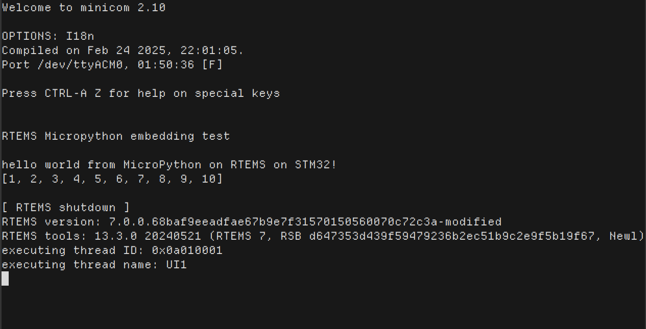
I have been able to set up an example for SPARC that uses MicroPython’s embed port with RTEMS. It is based on MircoPython’s own embedding example and the RTEMS “Hello World” application.
The Makefile micropython_embed.mk is used to generate the directory micropython_embed/ that contains the .c files for an embeddable MicroPython build. These are then used in mpy.c, where we have an example Python script stored as a string in example1, which is passed into mp_embed_exec_str() that runs it.
This should ideally be a baseline example that has an interactive MicroPython shell, but I am not sure if I can take user input in the SPARC simulator. I started with SPARC because it allowed me to quickly verify that it is possible to run MicroPython under RTEMS.
What should the next steps be?
This is what I have in mind from discussions on Discord so far:
setting up a baseline example that uses serial I/O to allow the user to interact with micropython
bringing this up on my stm32f407vet6, raspberry pi 5 or rpi pico.
exploring how MicroPython can be used to access RTEMS APIs
Something confusing to me is that the board refused to work (I was testing with a blinky earlier) with ROM size set to 512, which is the actual size of flash on this chip.
What I am focusing on next is getting serial input working so this can be an interactive prompt.
Something else I need to figure out is why I had to comment out #define CONFIGURE_UNLIMITED_OBJECTS and #define CONFIGURE_UNIFIED_WORK_AREAS in my init.c to make this example work on the board. I followed the error that followed and added a #define CONFIGURE_MAXIMUM_TASKS 1 to make it compile.
Good job! Some BSPs have configuration settings to override the memory origins and length. Then the defaults can be set in a user config.ini file while building RTEMS or added as BSP variant with a different BSP name to reflect the model
The original STM32F4 BSP is set up for an STM32F407VGT6 which has 1MB of FLASH. Your VET6 only has 512K. What would that do? Umm, nothing. The FLASH is used low to high, so the unavailable 512K would just cause a hard fault if you tried to read it.
The FLASH sits at location 0 at run time, but you have to write it at location 0x0800’0000.
I tried changing it to 512k as I mentioned earlier, is this not the correct way to do it? Even with a simple blinky, it only works if I leave that at 1M. Also yes I am writing to 0x08000000.
I’d set the quantity of FLASH to match your processor.
You’re working with a variant of the STM32F4 BSP. The original uses a VGT6 processor, you’ve got a VET6. By setting the FLASH size to match your processor, the linker can complain that you’ve run out of space. By leaving it at 1MB you can have a program that links, but when you try and program or read the FLASH above 512K on your processor, it will complain fatally.
In the BSP that I put together for the F767 I had to use 0x0800’0000. I don’t remember what triggered that change, since I wrote that BSP years ago but, yes, that alteration is cromulent.