Hello, I’m having trouble understanding the configuration of the SysTick timer in a BSP. I decided to write a BSP for the Artery AT32F437 microcontroller, which has a Cortex-M4 core. There is an existing BSP for STM32F4, and I chose to use it as a starting point.
In the source code, there is a line that sets BSP_ARMV7M_SYSTICK_FREQUENCY to 16,000,000 Hz, or 16 MHz.
I also reviewed the documentation on writing BSPs and drivers but found the sections on linker scripts and other relevant topics unhelpful, as they contain statements like “This chapter contains outdated and confusing information.” I will formulate my questions as a list:
I would greatly appreciate a concise explanation of how interrupts (specifically, the vector table I define in the BSP and the SysTick interrupts) are integrated into the RTEMS system from the BSP.
Is it correct to assume that the SysTick interrupt frequency for the STM32F4 configuration I referenced would be 16,000,000 times per second (this seems like it would significantly impact performance)?
If I configure the SysTick in the BSP, how do I inform the RTEMS kernel about the tick frequency?
I can only speak from my experience with ST’s STM32 series processors. What Artery did, well, you are now the go-to person.
So, I’ll assume a perfect clone…
The vector table is stored in FLASH at compile time, starting at location 0 for about 400 bytes. At startup the vector table is copied to RAM in bsp_interrupt_facility_initialize and the VTOR is set to point at this RAM based vector table. At run time, your code can register interrupt routines and their addresses are patched into the RAM vector table.
SysTick is normally a 1kHz interrupt, derived from an external crystal of 16MHz, divided down to give 1000 interrupts per second, within the precision of the crystal and load capacitors.
The ARM Cortex M4 core has calibration registers that are altered in _ARMV7M_Clock_initialize_early with a value calculated with the processor clock frequency (like 168MHz) and the required tick frequency, setting the SysTick to the frequency that you want.
SysTick is normally assumed to be 1kHz on STM32, so you’ll see that used quite a bit, and RTEMS uses 1kHZ unless you override it. At the bottom of init() you may see a define that looks like:
#define CONFIGURE_MICROSECONDS_PER_TICK 1000
This is the value that is used, along with the crystal frequency, and the PLL multiplier and divider values, to set the SysTick frequency.
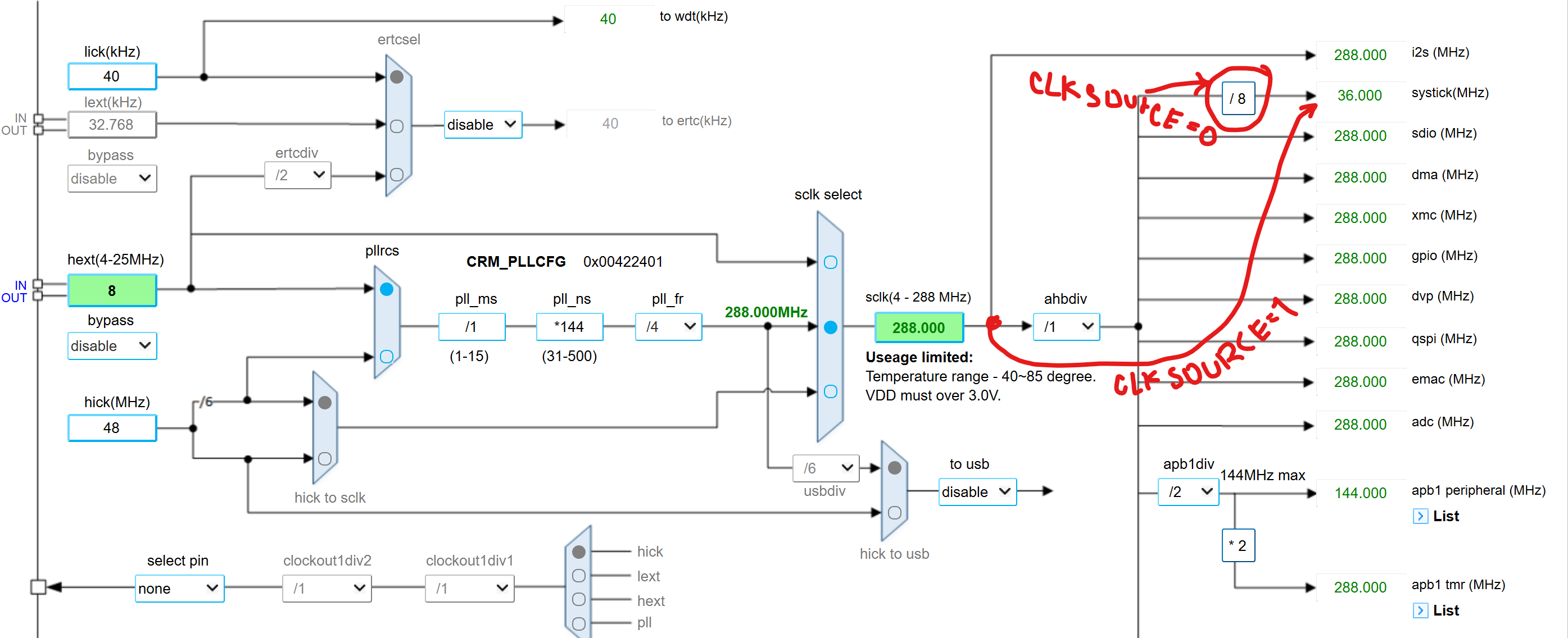
The macro BSP_ARMV7M_SYSTICK_FREQUENCY sets the SysTick clock frequency. It is important to note that some microcontrollers, such as the AT32F437ZMT, have clock dividers. Therefore, if you use a clock configuration generator, adjusting the SysTick divider may lead to errors. Since SysTick allows selecting the clock source, RTEMS for ARM by default (code below & clock tree) sets ARMV7M_SYSTICK_CSR_CLKSOURCE (CLKSOURCE = 1), indicating that the timer will be clocked directly from the core’s system clock signal (bypassing the divider).